|
Weblog: recent changes

in Dobrica Pavlinušić's random unstructured stuff
|
|
ESP32-Devkit-Pinout_19.pdf https://github.com/espressif/arduino-esp32/issues/544 ESP32 DEVKIT1schematic: SchematicsforESP32.pdf to get into bootloader mode (out of box) plug module in (red led will show that it has power from usb) and: press EN - press BOOT - release EN - release BOOT dpavlin@x200:/mnt/nuc/esptool$ ./esptool.py -p /dev/ttyUSB0 --chip esp32 read_mac esptool.py v2.7-dev Serial port /dev/ttyUSB0 Connecting........_ Chip is ESP32D0WDQ6 (revision 1) Features: WiFi, BT, Dual Core, 240MHz, VRef calibration in efuse, Coding Scheme None MAC: 3c:71:bf:aa:fc:24 Uploading stub... Running stub... Stub running... MAC: 3c:71:bf:aa:fc:24 Hard resetting via RTS pin... dpavlin@x200:/mnt/nuc/esptool$ ./esptool.py -p /dev/ttyUSB0 --chip esp32 chip_id esptool.py v2.7-dev Serial port /dev/ttyUSB0 Connecting........__ Chip is ESP32D0WDQ6 (revision 1) Features: WiFi, BT, Dual Core, 240MHz, VRef calibration in efuse, Coding Scheme None MAC: 3c:71:bf:aa:fc:24 Uploading stub... Running stub... Stub running... Warning: ESP32 has no Chip ID. Reading MAC instead. MAC: 3c:71:bf:aa:fc:24 Hard resetting via RTS pin... dpavlin@x200:/mnt/nuc/esptool$ ./esptool.py -p /dev/ttyUSB0 --chip esp32 flash_id esptool.py v2.7-dev Serial port /dev/ttyUSB0 Connecting........_____....._____....._____....._____. Chip is ESP32D0WDQ6 (revision 1) Features: WiFi, BT, Dual Core, 240MHz, VRef calibration in efuse, Coding Scheme None MAC: 3c:71:bf:aa:fc:24 Uploading stub... Running stub... Stub running... Manufacturer: 20 Device: 4016 Detected flash size: 4MB Hard resetting via RTS pin... setuphttps://docs.espressif.com/projects/esp-idf/en/latest/get-started/index.html#setup-toolchain dpavlin@nuc:/nuc/esp32$ wget https://dl.espressif.com/dl/xtensa-esp32-elf-linux64-1.22.0-80-g6c4433a-5.2.0.tar.gz dpavlin@nuc:/nuc/esp32$ tar tvf xtensa-esp32-elf-linux64-1.22.0-80-g6c4433a-5.2.0.tar.gz dpavlin@nuc:/nuc/esp32$ git clone --recursive https://github.com/espressif/esp-idf.git dpavlin@nuc:/nuc/esp32$ cd esp-idf/ dpavlin@nuc:/nuc/esp32/esp-idf$ cat env.sh export IDF_PATH=/nuc/esp32/esp-idf export PATH=/nuc/esp32/xtensa-esp32-elf/bin/:$PATH dpavlin@nuc:/nuc/esp32/esp-idf$ . env.sh dpavlin@nuc:/nuc/esp32/esp-idf$ python2 -m pip install --user -r $IDF_PATH/requirements.txt Requirement already satisfied: setuptools in /usr/lib/python2.7/dist-packages (from -r /nuc/esp32/esp-idf/requirements.txt (line 4)) (40.6.2) Requirement already satisfied: pyserial>=3.0 in /home/dpavlin/.local/lib/python2.7/site-packages (from -r /nuc/esp32/esp-idf/requirements.txt (line 8)) (3.4) Requirement already satisfied: future>=0.15.2 in /usr/lib/python2.7/dist-packages (from -r /nuc/esp32/esp-idf/requirements.txt (line 9)) (0.15.2) Requirement already satisfied: cryptography>=2.1.4 in /usr/lib/python2.7/dist-packages (from -r /nuc/esp32/esp-idf/requirements.txt (line 10)) (2.3) Requirement already satisfied: pyparsing>=2.0.3 in /usr/lib/python2.7/dist-packages (from -r /nuc/esp32/esp-idf/requirements.txt (line 11)) (2.2.0) WT32-ETH01https://www.raspberrypi.com/documentation/microcontrollers/rp2040.html pythonhttps://datasheets.raspberrypi.com/pico/getting-started-with-pico.pdf 1.8TFTST7755 pinout of connector, rp2040 pins
VCC https://github.com/boochow/MicroPython-ST7735 spi = SPI(0, baudrate=20000000, polarity=0, phase=0, sck=Pin(18), mosi=Pin(19), miso=Pin(16)) tft=TFT(spi,20,16,17) first stepsHere I will try to document correct order to read documentation to get setup for ULX3S: https://github.com/emard/ulx3s-bin/blob/master/README.md There is also useful things from chat at ULX3S Lobby udev ruleujproggit clone https://github.com/f32c/tools f32c-tools cd f32c-tools/ujprog/ dpavlin@x200:/mnt/nuc/FPGA/f32c-tools/ujprog$ rm ujprog dpavlin@x200:/mnt/nuc/FPGA/f32c-tools/ujprog$ make -f Makefile.linux cc -Wall -D__linux__ -std=gnu99 -static ujprog.c /usr/lib/x86_64-linux-gnu/libftdi.a /usr/lib/x86_64-linux-gnu/libusb.a -o ujprog dpavlin@x200:/mnt/nuc/FPGA/f32c-tools/ujprog$ sudo cp ujprog /usr/local/bin/
passthru to access esp32source at https://github.com/emard/ulx3s-passthru dpavlin@x200:/mnt/nuc/FPGA/ulx3s-bin/fpga/passthru/passthru-v20-85f$ ujprog -j flash ulx3s_85f_passthru.bit ULX2S / ULX3S JTAG programmer v 3.0.92 (built Nov 19 2019 10:55:50) Using USB cable: ULX3S FPGA 12K v3.0.3 [Wed Nov 20 18:02:01 2019] ftdi_sio ttyUSB0: FTDI USB Serial Device converter now disconnected from ttyUSB0 [Wed Nov 20 18:02:01 2019] ftdi_sio 1-5.2:1.0: device disconnected Programming: 100% Completed in 24.36 seconds. [Wed Nov 20 18:02:25 2019] usb 1-5.2: reset full-speed USB device number 56 using ehci-pci [Wed Nov 20 18:02:26 2019] ftdi_sio 1-5.2:1.0: FTDI USB Serial Device converter detected [Wed Nov 20 18:02:26 2019] usb 1-5.2: Detected FT-X [Wed Nov 20 18:02:26 2019] usb 1-5.2: FTDI USB Serial Device converter now attached to ttyUSB0 update size of your FPGAdpavlin@x200:/mnt/nuc/FPGA/ulx3s-bin$ usb-jtag/linux-amd64/ftx_prog --product "ULX3S FPGA 85K v3.0.3" power cycle board to get new usb id, test that it's supported by ujprog dpavlin@x200:/mnt/nuc/FPGA/ulx3s-bin$ ujprog -r esptool and esp32 booting problemsYou should be using ecptool from ulx3s-bin repository to quite @emard from https://gitter.im/ulx3s/Lobby#dark-theme OK then. If you have issues with ESP32 not booting with SD card but booting without SD card then then the fuse burn script from ulx3s-bin should be run. So far so good, you erased its flash, try linux. If no issue then can try to flash micropython and my new ESP32 OTA programmer ecp5.py end uftpd.py I have wisely taken some esptool.py which works and frozen it in ulx3s, versions change all the time and maybe you took something in the middle of development action :) install micropythonhttps://github.com/emard/esp32ecp5/ dpavlin@nuc:/nuc/FPGA$ git clone https://github.com/emard/esp32ecp5/ dpavlin@nuc:/nuc/FPGA$ cd esp32ecp5/ dpavlin@x200:/mnt/nuc/FPGA/esp32ecp5$ wget https://micropython.org/resources/firmware/esp32-idf3-20191120-v1.11-580-g973f68780.bin It's important to erase flash or micropyhton will complain about corrupt fat filesystem like:
FAT filesystem appears to be corrupted. If you had important data there, you
dpavlin@x200:/mnt/nuc/FPGA/esp32ecp5$ ../ulx3s-bin/esp32/serial-uploader/esptool.py --chip esp32 --port /dev/ttyUSB0 erase_flash
esptool.py v2.6-beta1
Serial port /dev/ttyUSB0
Connecting....
Chip is ESP32D0WDQ6 (revision 1)
Features: WiFi, BT, Dual Core, 240MHz, VRef calibration in efuse, Coding Scheme None
MAC: a4:cf:12:55:c5:60
Uploading stub...
Running stub...
Stub running...
Erasing flash (this may take a while)...
Chip erase completed successfully in 8.7s
Hard resetting via RTS pin...


dpavlin@x200:/mnt/nuc/FPGA/esp32ecp5$ ../ulx3s-bin/esp32/serial-uploader/esptool.py --chip esp32 --port /dev/ttyUSB0 --baud 460800 write_flash -z 0x1000 esp32-idf3-20191120-v1.11-580-g973f68780.bin
esptool.py v2.6-beta1
Serial port /dev/ttyUSB0
Connecting....
Chip is ESP32D0WDQ6 (revision 1)
Features: WiFi, BT, Dual Core, 240MHz, VRef calibration in efuse, Coding Scheme None
MAC: a4:cf:12:55:c5:60
Uploading stub...
Running stub...
Stub running...
Changing baud rate to 460800
Changed.
Configuring flash size...
Auto-detected Flash size: 4MB
Compressed 1240192 bytes to 783187...
Wrote 1240192 bytes (783187 compressed) at 0x00001000 in 18.7 seconds (effective 529.3 kbit/s)...
Hash of data verified.

Leaving...
Hard resetting via RTS pin...

dpavlin@x200:/mnt/nuc/FPGA/esp32ecp5$ microcom -p /dev/ttyUSB0
connected to /dev/ttyUSB0
Escape character: Ctrl-\
Type the escape character to get to the prompt.

>>>
> help()
Welcome to MicroPython on the ESP32!

For generic online docs please visit http://docs.micropython.org/

For access to the hardware use the 'machine' module:

import machine
pin12 = machine.Pin(12, machine.Pin.OUT)
pin12.value(1)
pin13 = machine.Pin(13, machine.Pin.IN, machine.Pin.PULL_UP)
print(pin13.value())
i2c = machine.I2C(scl=machine.Pin(21), sda=machine.Pin(22))
i2c.scan()
i2c.writeto(addr, b'1234')
i2c.readfrom(addr, 4)

Basic WiFi configuration:

import network
sta_if = network.WLAN(network.STA_IF); sta_if.active(True)
sta_if.scan()                             # Scan for available access points
sta_if.connect("<AP_name>", "<password>") # Connect to an AP
sta_if.isconnected()                      # Check for successful connection

Control commands:
  CTRL-A        -- on a blank line, enter raw REPL mode
  CTRL-B        -- on a blank line, enter normal REPL mode
  CTRL-C        -- interrupt a running program
  CTRL-D        -- on a blank line, do a soft reset of the board
  CTRL-E        -- on a blank line, enter paste mode

For further help on a specific object, type help(obj)
For a list of available modules, type help('modules')
webrepldpavlin@klin:/klin/FPGA$ git clone https://github.com/hyperglitch/webrepl You can send files from command-line: dpavlin@x200:/mnt/nuc/FPGA/webrepl$ ./webrepl_cli.py -p ulx3s ../esp32ecp5/ecp5.py 192.168.3.130:/ op:put, host:192.168.3.130, port:8266, passwd:ulx3s. ../esp32ecp5/ecp5.py -> /ecp5.py Remote WebREPL version: (1, 11, 0) Sent 22777 of 22777 bytes dpavlin@x200:/mnt/nuc/FPGA/webrepl$ ./webrepl_cli.py -p ulx3s ../esp32ecp5/uftpd.py 192.168.3.130:/ op:put, host:192.168.3.130, port:8266, passwd:ulx3s. ../esp32ecp5/uftpd.py -> /uftpd.py Remote WebREPL version: (1, 11, 0) Sent 19482 of 19482 bytes open source toolchainJust use kost's binary builds: https://github.com/alpin3/ulx3s/releases Or nightly builds: https://github.com/open-tool-forge/fpga-toolchain/releases this is old and needs update dpavlin@klin:/klin/FPGA$ git clone https://github.com/SymbiFlow/prjtrellis dpavlin@klin:/klin/FPGA/prjtrellis$ ./download-latest-db.sh dpavlin@klin:/klin/FPGA/prjtrellis$ cd libtrellis/ dpavlin@klin:/klin/FPGA/prjtrellis/libtrellis$ sudo apt-get install libpython3-dev libboost-python-dev libboost-filesystem-dev libboost-thread-dev libboost-program-options-dev dpavlin@klin:/klin/FPGA/prjtrellis/libtrellis$ cmake -DCMAKE_INSTALL_PREFIX=/usr/local . dpavlin@klin:/klin/FPGA/prjtrellis/libtrellis$ make sudo make install dpavlin@klin:/klin/FPGA/nextpnr$ cmake -DARCH=ecp5 -DBUILD_GUI=OFF -DTRELLIS_ROOT=../prjtrellis/ . make make install diamondhttps://github.com/jandob/lattice-diamond-archlinux/blob/master/eth0DummyToggle dockerhttps://gitter.im/ulx3s/Lobby?at=5dff4b08d2dadb38935c570a https://github.com/dok3r/diamond/ docker run -it -v /host/fpga:/fpga -- local /host/fpga will end up in /fpga in docker yes path will be fine you will be missing make so inside container you need to yum install make and yum install libxslt export ETHMAC=b0:5a:da:XX:XX:XX set your MAC docker run -it -v /media/internal/FPGA:/fpga -e LM_LICENSE_FILE=/fpga/license.dat --mac-address=$ETHMAC --privileged --ipc host -v /dev/bus/usb/:/dev/bus/usb/ dok3r/diamond:latest run docker yum install make libxslt go tu project inside fpga folder and find makefile for diamond and then just make then you share it with docker container with -v /yourHOSTfpgadir:/fpgadockerdir -e LM_LICENSE_FILE=/fpgadockerdir for version you need to use like this dok3r/diamond:version versions are here https://hub.docker.com/r/dok3r/diamond/tags docker run -it -v /media/internal/FPGA:/fpga -e LM_LICENSE_FILE=/fpga/license.dat --mac-address=$ETHMAC --privileged --ipc host -v /dev/bus/usb/:/dev/bus/usb/ dok3r/diamond:v3.7 like this Not understanding -v /media/internal/FPGA that is my local FPGA folder with samples and license.dat it will mount on docker /fpga and I see now that I need to share prjtrallis folder to docker so it can do ecppll docker run -it -v /media/internal/FPGA:/fpga -v /local/prjtrellis/libtrellis:/mt/scratch/tmp/openfpga/prjtrellis/libtrellis -e LM_LICENSE_FILE=/fpga/license.dat --mac-address=$ETHMAC --privileged --ipc host -v /dev/bus/usb/:/dev/bus/usb/ dok3r/diamond:v3.7 but for that we will need @kost we probably need ecppll and tools already there and compiled with centos- maybe just binaries NEShttps://gitter.im/ulx3s/Lobby?at=5de033f49319bb5190a9c3b6
oberonhttps://gitter.im/ulx3s/Lobby?at=5e007d1e8897197969e3331c
So, I have now managed to build oberon with diamond 3.7.
1. Build it with diamond 3.11, which fails
Thanks @kost for adding for adding make and libxslt to the docker image. It would be useful if you could patch the platform_check to allow versions before 3.11 to run on 5.* linux. docker pull dok3r/diamond:v3.7
woohoo! Cool
case $VERSION in It needs:
case $VERSION in
I did the docker pull to make sure I had the latest version. 21f repack from 25f imageecpunpack --input ulx3s_25.bit --textcfg ulx3s_12f.config --idcode 0x41111043 ecppack --input ulx3s_12f.config --bit ulxs3_12f.bit --idcode 0x21111043 compress bitstreamecppack --compress esp32ps2https://github.com/emard/esp32ps2 saxonsoclinux
Instructions at https://github.com/lawrie/saxonsoc-ulx3s-bin/tree/master/linux https://gitter.im/ulx3s/Lobby?at=5de8ba2f08d0c961b7f3a25f git clone https://github.com/SpinalHDL/buildroot.git -b saxon buildroot git clone https://github.com/SpinalHDL/linux.git -b vexriscv --depth 1 linux cd buildroot cp board/spinal/saxon_default/linux_nonet.config board/spinal/saxon_default/linux.config # Add extra options to board/spinal/saxon_default/linux.config make spinal_saxon_default_defconfig make linux-rebuild all -j$(nproc) output/host/bin/riscv32-linux-objcopy -O binary output/images/vmlinux output/images/Image # Make sure Image is at least 116KB less than 4MB 85f versionhttps://gitter.im/ulx3s/Lobby?at=5dea74995ac7f22fb57055ae https://github.com/lawrie/saxonsoc-ulx3s-bin/blob/master/linux/README.md https://github.com/lawrie/saxonsoc-ulx3s-bin/tree/master/linux/u-boot https://github.com/SpinalHDL/SaxonSoc/tree/dev/bsp/Ulx3sLinuxUboot ledshttps://gitter.im/ulx3s/Lobby?at=5dec101f46397c721ca4c814 #!/bin/sh cd /sys/class/gpio echo 488 > export echo out > gpio488/direction for i in 1 0 1 0 1 0 do sleep 0.1 echo $i > gpio488/value done slirphttps://gitter.im/ulx3s/Lobby?at=5df1467d0616d6515e20d197 modificationshttps://gitter.im/ulx3s/Lobby?at=5dfced993e3f133894ca9b4b u-boot config for 85f with 64M SDRAMModify bootcmd to include: load mmc 0:1 0x80000000 /boot/uImage load mmc 0:1 0x81EF0000 /boot/dtb fdt add 0x81EF0000 fdt memory 0x80000000 0x04000000 bootm 0x80000000 - 0x81EF0000 ppp networkingsmp supporthttps://gitter.im/ulx3s/Lobby?at=5f4ea80bd4f0f55ebbf6ec33 https://github.com/SpinalHDL/SaxonSoc/tree/dev-0.1/bsp/radiona/ulx3s/smp Instructions there need a bit of modification to run on blue 85f board with 64Mb of ram: # Sourcing the build script source SaxonSoc/bsp/radiona/ulx3s/smp/source.sh # Clone opensbi, u-boot, linux, buildroot, openocd saxon_clone # Build the FPGA bitstream saxon_standalone_compile bootloader CFLAGS_ARGS="-DSDRAM_TIMING=AS4C32M16SB_7TCN_ps" SDRAM_SIZE=64 saxon_netlist FPGA_SIZE=85 saxon_bitstream # Build the firmware saxon_opensbi saxon_uboot saxon_buildroot # Build the programming tools saxon_standalone_compile sdramInit CFLAGS_ARGS="-DSDRAM_TIMING=AS4C32M16SB_7TCN_ps" saxon_openocd Copy generated bitstream dpavlin@klin:/klin/FPGA/saxonsoc$ cp SaxonSoc/hardware/synthesis/radiona/ulx3s/smp/bin/toplevel.bit saxon.bit dpavlin@klin:/klin/FPGA/saxonsoc$ gzip -9 saxon.bit Transfer it using ftp ftp> put saxon.bit.gz local: saxon.bit.gz remote: saxon.bit.gz 200 OK 150 Opened data connection. 226 Done. 359484 bytes sent in 10.27 secs (34.1994 kB/s) ftp> site saxon.bit.gz u-boot will fail to boot if you have rootfs on second partition
SDRAM init
OpenSBI copy
U-Boot copy
OpenSBI boot

OpenSBI v0.6-8-gd7b62b8
   ____                    _____ ____ _____
  / __ \                  / ____|  _ \_   _|
 | |  | |_ __   ___ _ __ | (___ | |_) || |
 | |  | | '_ \ / _ \ '_ \ \___ \|  _ < | |
 | |__| | |_) |  __/ | | |____) | |_) || |_
  \____/| .__/ \___|_| |_|_____/|____/_____|
        | |
        |_|

Platform Name          : VexRiscv SMP simulation
Platform HART Features : RV32AIMS
Platform Max HARTs     : 4
Current Hart           : 0
Firmware Base          : 0x80f80000
Firmware Size          : 84 KB
Runtime SBI Version    : 0.2

MIDELEG : 0x00000222
MEDELEG : 0x0000b101


U-Boot 2020.07-08304-gd361dd3997 (Sep 05 2020 - 09:45:52 +0200)

DRAM:  32 MiB
MMC:   spi@10020000:mmc@1: 0
Loading Environment from FAT... Unable to use mmc 0:1... In:    serial@10010000
Out:   serial@10010000
Err:   serial@10010000
Net:   No ethernet found.
Hit any key to stop autoboot:  0
Wrong Image Format for bootm command
ERROR: can't get kernel image!
=>
https://github.com/dok3r/ulx3s-saxonsoc/wiki/SaxonSoc-on-ULX3s setenv bootcmd "load mmc 0:1 0x80000000 /boot/uImage;load mmc 0:1 0x80FF0000 /boot/dtb;fdt add 0x80FF0000;fdt memory 0x80000000 0x04000000;bootm 0x80000000 - 0x80FF0000" setenv bootargs "rootwait console=hvc0 root=/dev/mmcblk0p2 init=/sbin/init mmc_core.use_spi_crc=0" saveenv Lawrie Griffiths @lawrie Sep 01 21:59
The new SaxonSoc is now working on a 12F for me. Here are the instructions to build from source - https://github.com/SpinalHDL/SaxonSoc/tree/dev-0.1/bsp/radiona/ulx3s/smp ov7670 pmodhttps://github.com/goran-mahovlic/fpga-odysseus/tree/master/projects/OV7670-HDMI pmod pin mapping: https://github.com/goran-mahovlic/fpga-odysseus/blob/master/projects/OV7670-HDMI/ulx3s.lpf#L335 SCCB Pullup Resistorsfrom https://github.com/westonb/OV7670-Verilog The SCCB interface for the camera requires pull up resistors. You need to solder 4.7K resistors from the SIOD and SIOC pins on the camera to the 3.3V supply. You can do this yourself or have the staff in the EDS help you. ov7670_rgb_yuv_320x240_colorfilterhttps://github.com/JdeRobot/FPGA-robotics/tree/master/Projects/ComputerVision nmigenhttps://github.com/lawrie/ulx3s-nmigen-examples/blob/master/image/camtest.py csihttps://twitter.com/mad_archer_/status/1231249513509261313 https://github.com/libv/fosdem-video-linux litex(just links, need to test it)
spiramhttps://gitter.im/ulx3s/Lobby?at=5ef22d4c54d7862dc4a42395 @Speccery thereis also commandline "spiram.py" for some low-level inspection, so to reset TI this works for me spiram.poke(0x100008,bytearray(0xFC)) and to read bytes spiram.peek(0,16) bytearray(b'\x83\xe0\x00$\x83\xc0\t\x00\x83\xc0\n\x920\xaa\x04`') ledftx_prog --cbus 3 DRIVE_0 # green OFF ftx_prog --cbus 3 SLEEP # green ON if enumerated This is active after power cycle micropython blue led>>> from machine import Pin >>> led=Pin(5,Pin.OUT) >>> led.on() # upali plavu >>> led.off() # ugasi plavu micropythonfrom upysh import * TODOtry various projects for ulx3s c64part of https://github.com/lawrie/ulx3s_retro https://github.com/emard/ulx3s_c64 dpavlin@klin:/klin/FPGA/ulx3s_c64/proj$ time make FPGA_SIZE=25 tfmicro on LiteX/VexRiscvhttps://github.com/dlobato/tfmicro-on-litex-vexriscv ML CNN acceleratorhttps://github.com/BracketMaster/maeri kianRiscVhttps://gitAhub.com/splinedrive/kianRiscV/tree/master/linux_socs/kianv_mc_rv32ima_sv32/demo openFPGALoader -f -o $((1024*1024)) --board=ulx3s bootloader.bin infohttps://hackaday.com/2020/12/08/exploring-custom-firmware-on-xiaomi-thermometers/ https://github.com/atc1441/ATC_MiThermometer https://github.com/pvvx/ATC_MiThermometer Xiaomi Smart LCD Screen Digital Thermometer 2 Mijia Bluetooth Temperature Humidity Sensor Moisture Meter Mijia App https://www.aliexpress.com/item/1005002401046796.html LYWSD03MMC decode using gatttoolroot@rpi2:/home/pi# sudo hcitool lescan LE Scan ... A4:C1:38:D8:3F:9C ATC_D83F9C open source firmwarehttps://github.com/bentolor/xiaomi-mijia-bluetooth-firmware simple shell to send reading to influxhttps://github.com/dpavlin/air-quality/blob/master/ble-mijia.sh https://github.com/dpavlin/air-quality/blob/master/system/ble-mijia%40.service https://www.youtube.com/watch?v=NXKzFG61lNs Home Assistantconnected to home assistant using https://esphome.github.io/bluetooth-proxies/ get bindkey using https://atc1441.github.io/TelinkFlasher.html https://esphome.io/components/sensor/xiaomi_ble.html?highlight=xiaomi_ble#obtaining-the-bindkey
[core-ssh ~]$ tail -18 config/.storage/core.config_entries
      {
        "entry_id": "574243c45c4485523ec174e18cfcf1ad",
        "version": 1,
        "domain": "xiaomi_ble",
        "title": "Temperature/Humidity Sensor DC63 (LYWSD03MMC)",
        "data": {
          "bindkey": "a6da0c1d99200efe9c9afb8fd9a534ef"
        },
        "options": {},
        "pref_disable_new_entities": false,
        "pref_disable_polling": false,
        "source": "bluetooth",
        "unique_id": "A4:C1:38:90:DC:63",
        "disabled_by": null
      }
    ]
  }
flash new firmware to sensor https://github.com/pvvx/ATC_MiThermometer
open in chrome on android to flash firmware, dove-bootlog.txt Xtreme PC LXD8541 Chip PC Linux-based Thinx OS Product Specifications Xtreme PC LXD8541 Processor • Marvell Dove, Armada 510 800MHZ https://www.kernel.org/doc/html/v5.14/arm/marvell.html#dove-family-application-processor Memory • 1GB, DDR3 @ 800MHz Mass Storage • 2GB, High reliability eMMC NAND flash • Optional externally accessed MicroSD slot
Display Support • One DVI-I port
Resolutions • Single: Up to 1920x1200 Pixels @ true color (32 bit)
Video Player • Various video codecs, including: DivX HD, H.264 (MPEG4), WMV9/VC1
Audio Support • High Definition Audio Codec
sample rate Input / Output ports • 6 x USB 2.0 ports (2 front, 4 back) serialhttps://forum.doozan.com/read.php?2,67954,76099#msg-76099 Koen Re: Debian on Chip PC LXD8941 January 04, 2019 02:33PM Inside there is both a 4 pin and a 6 pin header. The 4 pin is the UART connection. With the power button towards you and the DVI connection away from you the connections are as follows: GND, TX, RX, VCC (from left to right). kernelLinux Kernel 6.6.2 MVEBU package and Debian armhf rootfs https://forum.doozan.com/read.php?2,32146 mkfs.ext3 -L rootfs /dev/sda1 mount /dev/sda1 /mnt/sda1/ cd /mnt/sda1/ tar xvf /nuc/armada/Debian-6.6.2-mvebu-tld-1-rootfs-bodhi.tar.bz2 3. Create uImage with DTB appended. root@nuc:/mnt/sda1# cd boot/ root@nuc:/mnt/sda1/boot# cp -a uImage uImage.orig root@nuc:/mnt/sda1/boot# cp -a zImage-6.6.2-mvebu-tld-1 zImage.fdt root@nuc:/mnt/sda1/boot# cat dts/dove-chip-lxd8941.dtb >> zImage.fdt root@nuc:/mnt/sda1/boot# mkimage -A arm -O linux -T kernel -C none -a 0x00008000 -e 0x00008000 -n Linux-6.6.2-mvebu-tld-1 -d zImage.fdt uImage Image Name: Linux-6.6.2-mvebu-tld-1 Created: Tue Dec 19 18:00:34 2023 Image Type: ARM Linux Kernel Image (uncompressed) Data Size: 5193798 Bytes = 5072.07 KiB = 4.95 MiB Load Address: 00008000 Entry Point: 00008000 insert usb stick into back 4 usb ports, front 2 won't find storage device on usb abort u-boot over serial and issue boot from usb:
setenv bootargs console=ttyS0,115200 root=LABEL=rootfs rootdelay=10 ${mtdparts} earlyprintk=serial
usb start; ext2load usb 0:1 0x3000000 /boot/uImage; ext2load usb 0:1 0x4000000 /boot/uInitrd
bootm 0x3000000 0x4000000
video output
DRM and framebuffer are not currently (as of 6.6) supported in upstream kernel according to messages at Let's try to boot with this dts but this does not work. u-boot enviromentfw_printenvroot@dove:~# cat /etc/fw_env.config # MTD device name Device offset Env. size Flash sector size Number of sectors /dev/mtd1 0x000000 0x010000 setup boot from usb
root@dove:~# fw_setenv bootusb 'setenv bootargs console=ttyS0,115200 root=LABEL=rootfs rootdelay=10 ${mtdparts} earlyprintk=serial ; usb start; ext2load usb 0:1 0x3000000 /boot/uImage; ext2load usb 0:1 0x4000000 /boot/uInitrd ; bootm 0x3000000 0x4000000'

root@dove:~# fw_printenv bootcmd
bootcmd=run bootmmc
root@dove:~# fw_setenv bootcmd bootusb
fw_setenv this doesn't work from booted debian system, re-try over serial on u-boot prompt:
MIC>> printenv usbboot
usbboot=usb start; sleep 3; ext2load usb 0:1 0x2000000 /boot/uImage; run usbargs;bootm 0x2000000
MIC>> setenv usbboot 'setenv bootargs console=ttyS0,115200 root=LABEL=rootfs rootdelay=10 ${mtdparts} earlyprintk=serial ; usb start; ext2load usb 0:1 0x3000000 /boot/uImage; ext2load usb 0:1 0x4000000 /boot/uInitrd ; bootm 0x3000000 0x4000000'
MIC>> printenv usbboot
usbboot=setenv bootargs console=ttyS0,115200 root=LABEL=rootfs rootdelay=10 ${mtdparts} earlyprintk=serial ; usb start; ext2load usb 0:1 0x3000000 /boot/uImage; ext2load usb 0:1 0x4000000 /boot/uInitrd ; bootm 0x3000000 0x4000000
MIC>> saveenv
Saving Environment to SPI Flash...
Erasing 0xc0000 - 0xd0000:      [Done]
Writing to SPI flash:           [Done]

MIC>> setenv bootcmd run usbboot
MIC>> saveenv
Saving Environment to SPI Flash...
Erasing 0xc0000 - 0xd0000:      [Done]
Writing to SPI flash:           [Done]
power buttonseemes like it's on gpio 25 apt install gpiod root@dove:/home/dpavlin# gpioget 0 0 1 2 3 4 5 12 13 14 15 16 17 18 19 20 21 22 23 24 25 26 27 28 29 30 31 1 0 1 1 0 0 0 0 1 1 1 0 1 0 0 0 0 1 0 1 0 0 0 0 0 0 root@dove:/home/dpavlin# gpioget 0 0 1 2 3 4 5 12 13 14 15 16 17 18 19 20 21 22 23 24 25 26 27 28 29 30 31 1 0 1 1 0 0 0 0 1 1 1 0 1 0 0 0 0 1 0 0 0 0 0 0 0 0 root@dove:/home/dpavlin# gpiomon 0 25 event: FALLING EDGE offset: 25 timestamp: [ 1466.369262333] event: FALLING EDGE offset: 25 timestamp: [ 1466.632278096] event: RISING EDGE offset: 25 timestamp: [ 1467.188375662] event: RISING EDGE offset: 25 timestamp: [ 1468.390585489] event: FALLING EDGE offset: 25 timestamp: [ 1470.143645190] event: RISING EDGE offset: 25 timestamp: [ 1471.752436499] event: FALLING EDGE offset: 25 timestamp: [ 1473.233499601] event: RISING EDGE offset: 25 timestamp: [ 1474.560678725] TV power button
show_name: true
show_icon: true
type: button
tap_action:
  action: call-service
  service: mqtt.publish
  data:
    topic: cmnd/ir/IRSend
    payload: '{"protocol": "NEC","bits": 32, "data": 0x20DF10EF}'
  target: {}
icon: mdi:television
https://github.com/raphaelbs/esp32-cam-ai-thinker/blob/master/docs/about-esp32-cam.md connection, flashingconnected to pl2303 serial
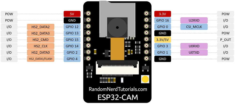 To program the board, I userd jumper to jump GPIO0 with GND pin next to it. improved example apphttps://github.com/easytarget/esp32-cam-webserver cp myconfig.sample.h myconfig.h vi myconfig.h dpavlin@nuc:/nuc/esp32/esp32-cam-webserver$ platformio run dpavlin@nuc:/nuc/esp32/esp32-cam-webserver$ pio run -t upload --upload-port /dev/ttyUSB2 "/home/dpavlin/.platformio/penv/bin/python" "/home/dpavlin/.platformio/packages/tool-esptoolpy/esptool.py" \ --chip esp32 --port "/dev/ttyUSB3" --baud 460800 --before default_reset --after hard_reset \ write_flash -z --flash_mode dio --flash_freq 40m --flash_size detect \ 0x1000 /home/dpavlin/.platformio/packages/framework-arduinoespressif32/tools/sdk/bin/bootloader_dio_40m.bin \ 0x8000 /nuc/esp32/esp32-cam-webserver/.pio/build/esp32cam/partitions.bin \ 0xe000 /home/dpavlin/.platformio/packages/framework-arduinoespressif32/tools/partitions/boot_app0.bin \ 0x10000 .pio/build/esp32cam/firmware.bin timelapseocr on devicehttps://github.com/jomjol/AI-on-the-edge-device https://github.com/jomjol/AI-on-the-edge-device/wiki/Installation
Remove glue from lens (very hard, using sharp knife), and rotate lens by 45 degrees until dpavlin@nuc:/nuc/esp32/AI-on-the-edge-device$ vi sd-card/wlan.ini dpavlin@nuc:/nuc/esp32/AI-on-the-edge-device/code$ pio run dpavlin@nuc:/nuc/esp32/AI-on-the-edge-device/code$ pio run -v -t upload --upload-port /dev/ttyUSB3 "/home/dpavlin/.platformio/penv/bin/python" "/home/dpavlin/.platformio/packages/tool-esptoolpy/esptool.py" \ --chip esp32 --port "/dev/ttyUSB3" --baud 460800 --before default_reset --after hard_reset \ write_flash -z --flash_mode dio --flash_freq 40m --flash_size detect \ 0x1000 /nuc/esp32/AI-on-the-edge-device/code/.pio/build/esp32cam/bootloader.bin \ 0x8000 /nuc/esp32/AI-on-the-edge-device/code/.pio/build/esp32cam/partitions.bin \ 0xd000 /nuc/esp32/AI-on-the-edge-device/code/.pio/build/esp32cam/ota_data_initial.bin \ 0x10000 .pio/build/esp32cam/firmware.bin # original flashing instructions esptool write_flash 0x01000 bootloader.bin 0x08000 partitions.bin 0x10000 firmware.bin # download raw picture wget 192.168.3.112/img_tmp/raw.jpg old, obsolete problemsIt seems that my module is usually known as AI thinker variant. It has terrible picture which starts with huge green bias. It also doesn't work for me in resolutions below 1024x768 (in current esp32 example as of 2019-08-02). Plugging it into external 5V power supply did not helped much. To solve green tint, I just left esp32cam module plugged in whole day and night. I guess that image sensor got discharged during night, but next day picture was fine. Problem with image resolution was fixed by updating to more recent version of ESP32 support for Arduino (as of 2020-04-20 it works fine) Home Assistanthttps://jamesachambers.com/cheap-esp32-cam-home-assistant-esphome-camera-guide/
esphome:
  name: esp32cam
  friendly_name: esp32cam

esp32:
  board: esp32cam
  framework:
    type: arduino

# Enable logging
logger:
  level: VERBOSE
  tx_buffer_size: 256

# Enable Home Assistant API
api:
  encryption:
    key: "MsJJJiDv9FTjZ1w8dfoy3Z8cQWjGOsk0m4Wgge0B+8w="
  services:  # change camera parameters on-the-fly
  - service: camera_set_param
    variables:
      name: string
      value: int
    then:
      - lambda: |-
          bool state_return = false;
          if (("contrast" == name) && (value >= -2) && (value <= 2)) { id(espcam).set_contrast(value); state_return = true; }
          if (("brightness" == name) && (value >= -2) && (value <= 2)) { id(espcam).set_brightness(value); state_return = true; }
          if (("saturation" == name) && (value >= -2) && (value <= 2)) { id(espcam).set_saturation(value); state_return = true; }
          if (("special_effect" == name) && (value >= 0U) && (value <= 6U)) { id(espcam).set_special_effect((esphome::esp32_camera::ESP32SpecialEffect)value); state_return = true; }
          if (("aec_mode" == name) && (value >= 0U) && (value <= 1U)) { id(espcam).set_aec_mode((esphome::esp32_camera::ESP32GainControlMode)value); state_return = true; }
          if (("aec2" == name) && (value >= 0U) && (value <= 1U)) { id(espcam).set_aec2(value); state_return = true; }
          if (("ae_level" == name) && (value >= -2) && (value <= 2)) { id(espcam).set_ae_level(value); state_return = true; }
          if (("aec_value" == name) && (value >= 0U) && (value <= 1200U)) { id(espcam).set_aec_value(value); state_return = true; }
          if (("agc_mode" == name) && (value >= 0U) && (value <= 1U)) { id(espcam).set_agc_mode((esphome::esp32_camera::ESP32GainControlMode)value); state_return = true; }
          if (("agc_value" == name) && (value >= 0U) && (value <= 30U)) { id(espcam).set_agc_value(value); state_return = true; }
          if (("agc_gain_ceiling" == name) && (value >= 0U) && (value <= 6U)) { id(espcam).set_agc_gain_ceiling((esphome::esp32_camera::ESP32AgcGainCeiling)value); state_return = true; }
          if (("wb_mode" == name) && (value >= 0U) && (value <= 4U)) { id(espcam).set_wb_mode((esphome::esp32_camera::ESP32WhiteBalanceMode)value); state_return = true; }
          if (("test_pattern" == name) && (value >= 0U) && (value <= 1U)) { id(espcam).set_test_pattern(value); state_return = true; }
          if (true == state_return) {
            id(espcam).update_camera_parameters();
          }
          else {
            ESP_LOGW("esp32_camera_set_param", "Error in name or data range");
          }

ota:
  password: "09e4b58a1d186b8b33d100548f33d796"

wifi:
  ssid: !secret wifi_ssid
  password: !secret wifi_password

  power_save_mode: none

  # Enable fallback hotspot (captive portal) in case wifi connection fails
  ap:
    ssid: "Esp32Cam Fallback Hotspot"
    password: "GTIKgjitx2Re"

captive_portal:

# Example configuration entry
esp32_camera:
  id: espcam
  name: esp-cam
  external_clock:
    pin: GPIO0
    frequency: 20MHz
  i2c_pins:
    sda: GPIO26
    scl: GPIO27
  data_pins: [GPIO5, GPIO18, GPIO19, GPIO21, GPIO36, GPIO39, GPIO34, GPIO35]
  vsync_pin: GPIO25
  href_pin: GPIO23
  pixel_clock_pin: GPIO22
  power_down_pin: GPIO32

  resolution: 800x600
  jpeg_quality: 10  # max. 63
  max_framerate: 1.0fps
  idle_framerate: 0.2fps
  vertical_flip: true
  horizontal_mirror: false
  brightness: 2 # -2 to 2
  contrast: 1 # -2 to 2
  special_effect: none
  # exposure settings
  aec_mode: auto
  aec2: false
  ae_level: 0
  aec_value: 300
  # gain settings
  agc_mode: auto
  agc_gain_ceiling: 2x
  agc_value: 0
  # white balance setting
  wb_mode: auto
output:
# white LED
  - platform: ledc
    channel: 2
    pin: GPIO4
    id: espCamLED
# red status light
  - platform: gpio
    pin:
      number: GPIO33
      inverted: True
    id: gpio_33
light:
  - platform: monochromatic
    output: espCamLED
    name: esp-cam light
  - platform: binary
    output: gpio_33
    name: esp-cam led
switch:
  - platform: restart
    name: esp-cam restart
binary_sensor:
  - platform: status
    name: esp-cam status
CJMCU-811 CCS811 Carbon Monoxide CO VOCs Air Quality Digital Gas Sensor pins
VCC this is directly connected to the IC (there is no voltage regulator on board), connect this to 3.3V firmware upgradehttps://github.com/maarten-pennings/CCS811/tree/master/examples/ccs811flash dpavlin@nuc:~/Arduino/libraries$ git clone https://github.com/maarten-pennings/CCS811 Wiring for ESP8266 NodeMCU boards: VDD to 3V3, GND to GND, SDA to D2, SCL to D1, nWAKE to D3 (or GND) Serial output with sensor out of (china) bag: setup: Starting CCS811 basic demo setup: ccs811 lib version: 12 setup: hardware version: 12 setup: bootloader version: 1000 setup: application version: 1100 CCS811: waiting for (new) data CCS811: waiting for (new) data CCS811: eco2=0 ppm etvoc=0 ppb CCS811: eco2=0 ppm etvoc=0 ppb CCS811: eco2=0 ppm etvoc=0 ppb CCS811: eco2=400 ppm etvoc=0 ppb CCS811: eco2=400 ppm etvoc=0 ppb CCS811: eco2=400 ppm etvoc=0 ppb CCS811: eco2=400 ppm etvoc=0 ppb CCS811: eco2=400 ppm etvoc=0 ppb CCS811: eco2=400 ppm etvoc=0 ppb CCS811: eco2=400 ppm etvoc=0 ppb CCS811: eco2=400 ppm etvoc=0 ppb CCS811: eco2=400 ppm etvoc=0 ppb CCS811: eco2=400 ppm etvoc=0 ppb CCS811: eco2=400 ppm etvoc=0 ppb CCS811: eco2=400 ppm etvoc=0 ppb CCS811: eco2=400 ppm etvoc=0 ppb CCS811: eco2=400 ppm etvoc=0 ppb CCS811: eco2=400 ppm etvoc=0 ppb upgrade serial outputStarting CCS811 flasher setup: library version: 12 setup: hardware version: 12 setup: bootloader version: 1000 setup: application version: 1100 setup: comment-out this code line if you want to flash loop: ended ... loop: ended ... loop: ended ... loop: ended ... loop: ended ... loop: ended ... loop: ended ... loop: ended ... ccs811: ping ok ccs811: reset ok ccs811: status (reset1) 10 ok ccs811: app-erase ok ccs811: status (app-erase) 40 ok ccs811: writing 5120 ................................................................ 4608 ccs811: writing 4608 ................................................................ 4096 ccs811: writing 4096 ................................................................ 3584 ccs811: writing 3584 ................................................................ 3072 ccs811: writing 3072 ................................................................ 2560 ccs811: writing 2560 ................................................................ 2048 ccs811: writing 2048 ................................................................ 1536 ccs811: writing 1536 ................................................................ 1024 ccs811: writing 1024 ................................................................ 512 ccs811: writing 512 ................................................................ 0 ccs811: app-verify ok ccs811: status (app-verify) 30 ok ccs811: reset2 ok ccs811: status (reset2) 10 ok setup: Starting CCS811 basic demo setup: ccs811 lib version: 12 setup: hardware version: 12 setup: bootloader version: 1000 setup: application version: 2000 CCS811: waiting for (new) data CCS811: waiting for (new) data CCS811: waiting for (new) data CCS811: waiting for (new) data CCS811: eco2=400 ppm etvoc=0 ppb CCS811: eco2=400 ppm etvoc=0 ppb CCS811: eco2=409 ppm etvoc=1 ppb CCS811: eco2=414 ppm etvoc=2 ppb CCS811: eco2=400 ppm etvoc=0 ppb CCS811: eco2=400 ppm etvoc=0 ppb CCS811: eco2=400 ppm etvoc=0 ppb CCS811: eco2=407 ppm etvoc=1 ppb CCS811: eco2=400 ppm etvoc=0 ppb CCS811: eco2=400 ppm etvoc=0 ppb CCS811: eco2=400 ppm etvoc=0 ppb CCS811: eco2=408 ppm etvoc=1 ppb CCS811: eco2=414 ppm etvoc=2 ppb CCS811: eco2=417 ppm etvoc=2 ppb CCS811: eco2=414 ppm etvoc=2 ppb CCS811: eco2=408 ppm etvoc=1 ppb CCS811: eco2=408 ppm etvoc=1 ppb CCS811: eco2=400 ppm etvoc=0 ppb CCS811: eco2=400 ppm etvoc=0 ppb CCS811: eco2=400 ppm etvoc=0 ppb CCS811: eco2=406 ppm etvoc=0 ppb CCS811: eco2=400 ppm etvoc=0 ppb Since my sensor is new, I used firmware 2.0.0 to allow initial burn-in compensation. temperature compensationesphome
esphome:
  name: ccs811
  friendly_name: ccs811

esp8266:
  board: nodemcuv2

# Enable logging
logger:

# Enable Home Assistant API
api:
  encryption:
    key: "XXXXXXXXXXXXXXXXXXXXXXXXXXXXXXXXXXXXXXXXXXX="

ota:
  password: "XXXXXXXXXXXXXXXXXXXXXXXXXXXXXXXX"

wifi:
  ssid: !secret wifi_ssid
  password: !secret wifi_password

  # Enable fallback hotspot (captive portal) in case wifi connection fails
  ap:
    ssid: "Ccs811 Fallback Hotspot"
    password: "XXXXXXXXXXXX"

captive_portal:

  # Example configuration entry
i2c:
  sda: D2
  scl: D1

sensor:
  - platform: ccs811
    eco2:
      name: "CCS811 eCO2 Value"
    tvoc:
      name: "CCS811 Total Volatile Organic Compound"
    address: 0x5A
    update_interval: 15s

  - platform: bme280
    temperature:
      name: "BME280 Temperature"
      id: bme280_temperature
    pressure:
      name: "BME280 Pressure"
      id: bme280_pressure
    humidity:
      name: "BME280 Relative Humidity"
      id: bme280_humidity
    address: 0x76
    update_interval: 15s
RCWL-0516 is a doppler radar microwave motion sensor module which can act as an alternative to a PIR motion sensor. https://github.com/jdesbonnet/RCWL-0516 https://community.home-assistant.io/t/custom-sensor-using-nodemcu-and-rcwl-0516-solved/313635/13 HDMI expander
|
Weblog Archives
|